TIFF 6.0 Specification
Final—June 3, 1992
Input Picture
Output Picture
Forward Transform
8x8 2-D DCT
Inverse Transform
8x8 2-D IDCT
Uniform Quantization
Up to 4 Quant. Tables
Inverse Quantization
Receives 4 Tables
1-D DC Prediction
1-D DC Prediction
Entropy Coding
2 DC and AC Tables
Entropy Decoding
Receives 2+2 Tables
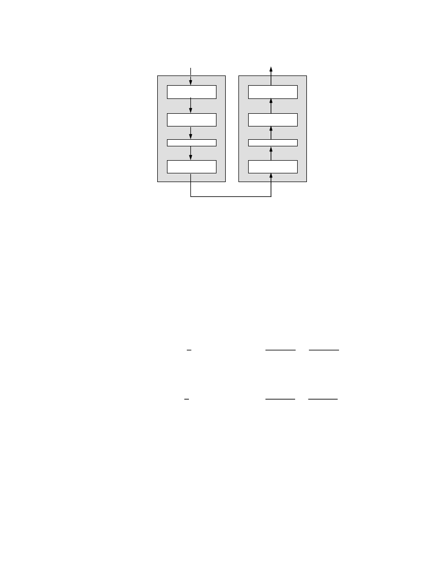
Figure 1. Baseline Process Encoder and Decoder
A functional block diagram of the Baseline encoding and decoding processes is
contained in Figure 1. Encoder operation consists of dividing each component of
the input image into 8x8 blocks, performing the two-dimensional DCT on each
block, quantizing each DCT coefficient uniformly, subtracting the quantized DC
coefficient from the corresponding term in the previous block, and then entropy
coding the quantized coefficients using variable length codes (VLCs). Decoding
is performed by inverting each of the encoder operations in the reverse order.
The DCT
Before performing the foward DCT, input pixels are level-shifted so that they
range from -128 to +127. Blocks of 8x8 pixels are transformed with the two-
dimensional 8x8 DCT:
1
π
(2x+1)u
π
(2y+1)v
F(u,v) = 4 C(u)C(v)
∑∑
f(x,y) cos
cos
16
16
and blocks are inverse transformed by the decoder with the Inverse DCT:
1
π
(2x+1)u
π
(2y+1)v
f(x,y) = 4
∑ ∑
C(u)C(v) F(u,v) cos
cos
16
16
with
u, v, x, y
= 0, 1, 2, ... 7
where
x, y
= spatial coordinates in the pel domain
u, v
= coordinates in the transform domain
C(u), C(v)
= 1 / sqrt(2)
for
u, v
= 0
1
otherwise
96