TIFF 6.0 Specification
Final—June 3, 1992
6
7
8
9
10
11
12
-63..-32, 32..63
-127..-64, 64..127
-255..-128, 128..255
-511..-256, 256..511
-1023..-512, 512..1023
-2047..-1024, 1024..2047
-4095..-2048, 2048..4095
SSSS is then coded from the selected DC VLC table. The VLC is followed by a
VLI having SSSS bits that represents the value of the differential DC coefficient
itself. If the coefficient is positive, the VLI is simply the low-order bits of the
coefficient. If the coefficient is negative, then the VLI is the low-order bits of the
coefficient-1.
AC Coefficient Coding
In a similar fashion, AC coefficients are coded with alternating VLC and VLI
codes. The VLC table, however, is a two-dimensional table that is indexed by a
composite 8-bit value. The lower 4 bits of the 8-bit value, i.e. the column index, is
the number of significant bits, SSSS, of a non-zero AC coefficient. SSSS is com-
puted through the same table as that used for coding the DC coefficient. The
higher-order 4 bits, the row index, is the number of zero coefficients, NNNN, that
precede the non-zero AC coefficient. The first column of the two-dimensional
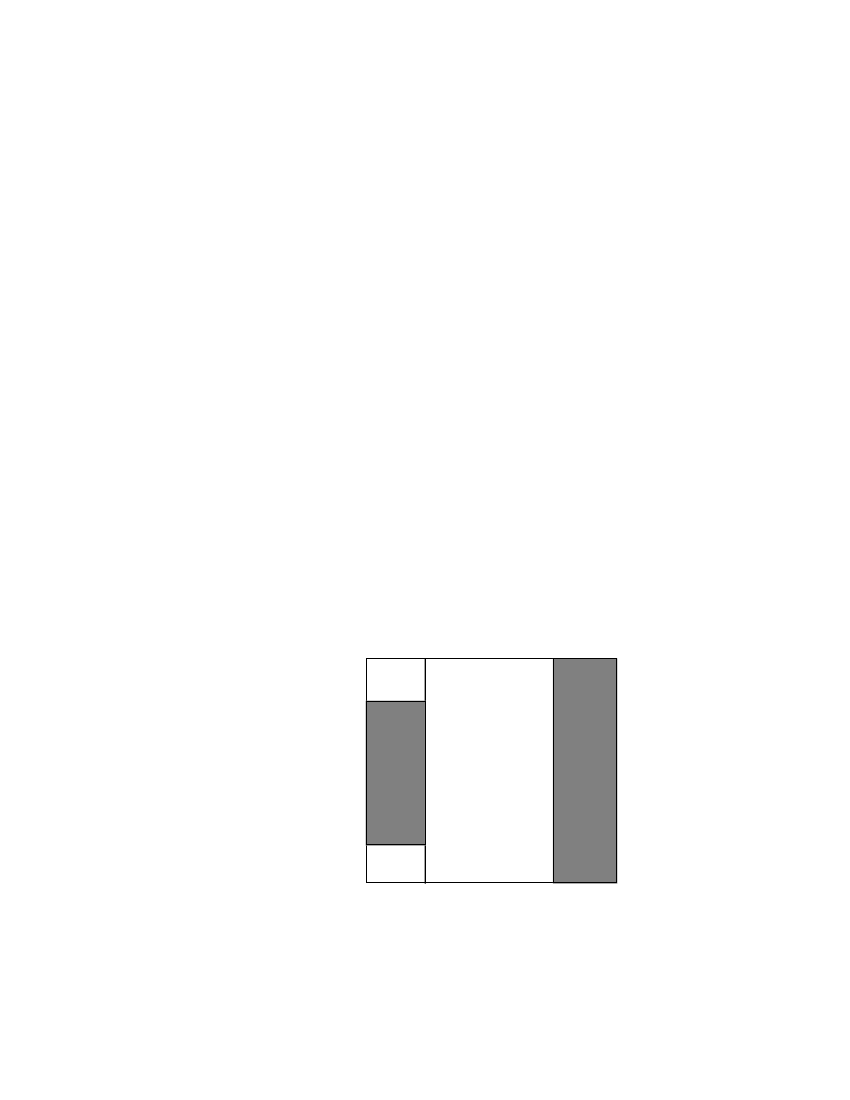
coding table contains codes that represent control functions. Figure 4 illustrates
the general structure of the AC coding table.
SSSS - Size of Non-Zero AC Coefs
01 2…
10 11…15
0
EOB
NNNN
Length .
of
Zero
Run
.
.
15
ZRL
Figure 4. 2-D Run-Size Value Array for AC Coefs
The shaded portions are undefined in the baseline process
The flow chart in Figure 5 specifies the AC coefficient coding procedure. AC
coefficients are coded by traversing the block in the zig-zag sequence and count-
99